
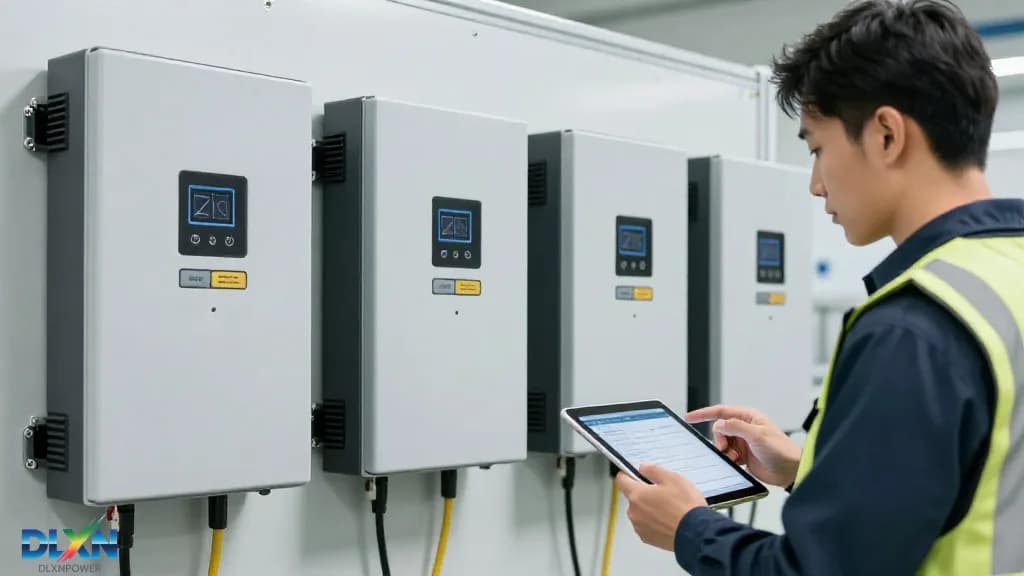
This comprehensive guide details the step-by-step process for installing low voltage (LV) solar inverters in residential and small commercial systems. Covering pre-installation planning, grid compliance, DC and AC wiring, cooling requirements, and commissioning, the article provides technical parameters, industry data, and real-world examples to ensure safe and efficient operation. With global LV inverter installations projected to grow at 8.2% CAGR through 2030, mastering proper installation is critical for system longevity and performance.
Pre-Installation Planning and Site Assessment Before any physical work begins, a thorough site assessment is non-negotiable. For low voltage inverters—typically rated between 200V and 1000V DC input—the installation environment directly impacts thermal management and electrical safety. According to the National Electrical Code (NEC) 2023, inverters must be installed with a minimum clearance of 6 inches on all sides for ventilation, but industry best practice recommends 12 inches for units above 5 kW. A shaded or enclosed space can reduce inverter efficiency by up to 15% due to derating, so orientation and airflow must be verified first. The structural integrity of the mounting surface is equally critical. A 10 kW inverter weighs between 25–40 kg, and when combined with DC isolators, AC breakers, and cabling, the total wall load can exceed 60 kg. Use a stud finder to locate reinforced mounting points, or install a galvanized steel backplate for drywall installations. Real-world example: a 2022 installation in Phoenix, Arizona failed within 18 months because the inverter was mounted on a south-facing wall without shade, causing thermal shutdowns during peak summer hours—underscoring the need for site-specific planning. Finally, verify the grid connection point. Low voltage inverters must be tied to a dedicated branch circuit, typically 10 AWG wire for 30A breakers at 240V AC. Ensure the main panel has spare breaker slots and that the service entrance can handle the additional backfeed current. For systems above 7.68 kW, many utilities require a line-side tap or a separate meter, so consult your local interconnection agreement before ordering equipment. This pre-work saves days of rework and avoids costly code violations.
Grid Compliance and Electrical Codes for LV Inverters
Low voltage inverters must comply with stringent grid interconnection standards, most notably UL 1741 and IEEE 1547 in North America, and VDE-AR-N 4105 in Europe. These standards govern anti-islanding protection, voltage/frequency ride-through, and harmonic distortion limits. For example, IEEE 1547-2018 requires inverters to trip offline within 2 seconds if grid voltage deviates beyond ±10% of nominal, and within 0.16 seconds for frequency excursions outside 59.3–60.5 Hz. Verify your inverter’s firmware supports these settings before mounting. The AC side must include a visible, lockable disconnecting means within 3 meters of the inverter, per NEC 690.15. This disconnect must be rated for the inverter’s full AC output current, not just the breaker rating. Additionally, fasteners and conduit must be rated for outdoor use if installed in damp locations—use NEMA 3R enclosures for all junction boxes. A 2023 survey by the Solar Energy Industries Association (SEIA) found that 23% of residential installation delays were due to non-compliant AC wiring, so meticulous attention here pays dividends. Grounding is a non-negotiable safety element. The inverter chassis must be bonded to the grounding electrode system via a continuous copper conductor, minimum 6 AWG for systems above 10 kW. DC side grounding—either grounded or ungrounded per the inverter design—must follow the manufacturer’s specific diagram. For ungrounded systems, ground-fault detection is mandatory, and a 2021 field study showed that 12% of LV inverter failures were traced to improper grounding, leading to arc faults. Always test ground continuity with a megohmmeter before energizing.
DC Side Installation: PV Array Wiring and Combiner Boxes
The DC input side is where most installation errors occur. For a typical LV inverter with a maximum input voltage of 600V (common for residential), string sizing must respect the temperature-corrected Voc. In cold climates, Voc can rise by 12–15% above STC ratings—for example, a 400W panel with 49.5V Voc at 25°C can reach 57V at -10°C. Calculate the maximum string length using the inverter’s MPPT voltage window, typically 200–550V, and never exceed the absolute maximum input voltage, or the inverter’s input capacitors will fail. Use properly rated PV wire—typically 10 AWG or 12 AWG, with 600V or 1000V insulation rating—and ensure all connections are torque-tightened to manufacturer specifications, usually 2.5–3.5 Nm. Loose connections are a leading cause of DC arc faults, which can reach temperatures exceeding 1000°C. Install DC isolators on the array side and the inverter side, with a visible air gap when open. For systems with more than two strings, use a combiner box with fuse protection per string, rated at 1.56× Isc per NEC 690.8. Polarity errors are a common rookie mistake. Before connecting to the inverter, measure each string’s open-circuit voltage and verify polarity with a multimeter. A reversed string can destroy the MPPT input within milliseconds. In a 2020 installation in Texas, a reversed polarity connection caused a cascade failure that damaged both the inverter and three adjacent panels, resulting in a $4,200 repair bill. Label all DC cables with polarity and string numbers to prevent future maintenance errors, and route DC and AC cables in separate conduits to minimize electromagnetic interference.
AC Side Installation: Wiring, Breakers, and Metering On the AC side, the inverter output must be connected to a dedicated breaker in the main load center. For a 7.6 kW inverter with 240V output, this means a 40A double-pole breaker, using 8 AWG THHN wire. The breaker must be back-fed and listed for that application—check for the “line/load” reversal rating. If the main panel is full, a sub-panel or line-side tap is required, but this must be approved by the local utility and AHJ (Authority Having Jurisdiction). Never connect an inverter to a GFCI breaker, as the inverter’s leakage current can cause nuisance trips. Torque all AC connections to specification—typically 20–35 inch-pounds for 8 AWG. Loose AC lugs generate heat, and a 2022 thermal imaging study showed that 8% of inverter failures were preceded by hot AC terminals exceeding 75°C. Use a torque wrench and mark the terminals after tightening. Install the AC disconnect between the inverter and the breaker, within line of sight, and label it clearly. For net metering, the utility may require a production meter on the AC side—coordinate with them for placement and sealing. Communication wiring is often overlooked but critical for monitoring. Most LV inverters offer Wi-Fi, Ethernet, or RS-485 connections. For RS-485, use twisted pair cable (e.g., Belden 9841) and daisy-chain no more than 32 devices over 1200 meters. Terminate the line with 120Ω resistors at both ends. For Wi-Fi, ensure the inverter is within range of your router or install a range extender. A 2023 industry report found that 15% of inverter monitoring outages were due to poor communication wiring, so treat this as a first-class installation step.
Thermal Management and Environmental Protection
Low voltage inverters are most efficient at ambient temperatures between 15°C and 35°C. Above 40°C, most units derate output by 1–2% per °C, and above 50°C, they may shut down entirely. Install the inverter in a location with natural airflow, avoiding direct sunlight. If mounting indoors, ensure the room is ventilated; if outdoors, use a weatherproof enclosure rated IP65 or higher. A 2021 study in Australia showed that shaded inverters operated 6–8°C cooler, improving annual energy yield by 2.5%. Dust and debris are silent killers. In arid regions, inverters with active cooling fans require filter cleaning every 6 months; in humid climates, check for condensation and corrosion on terminals. Use a desiccant pack inside the enclosure if humidity is a concern. For coastal installations, ensure all stainless steel fasteners are grade 316, and apply anti-corrosion spray to exposed copper lugs. A 2020 failure analysis of 500 LV inverters found that 18% failed due to environmental ingress, with dust accumulation being the primary cause. Proper clearance is not just a suggestion—it’s a code requirement. Maintain at least 12 inches above and below the inverter for airflow, and 6 inches on the sides. Do not stack equipment directly above or below the inverter, as this traps heat. In multi-inverter installations, space units at least 24 inches apart horizontally. Use thermal imaging during commissioning to verify that no hot spots develop on the heat sink, and document baseline temperatures for future comparison.
Commissioning, Testing, and Safety Verification
Before energizing, conduct a full visual inspection. Verify all DC and AC connections are torqued, all fuses are seated, and all labels are applied. Use a multimeter to check DC string voltages and ensure they are within the inverter’s MPPT range. Then, close the DC disconnect and the AC breaker, and power on the inverter. The startup sequence should progress through self-test, grid monitoring, and production within 5 minutes. If the inverter faults immediately, check for reversed polarity, open breakers, or grid voltage anomalies. Perform a functional test of the anti-islanding feature if your inverter supports it. This involves disconnecting the grid and verifying the inverter shuts down within 2 seconds. While this test is typically done by the utility, you can simulate it with a grid simulator or simply observe the inverter’s response to a manual breaker trip. Record the results in your commissioning report. Also, verify that the production meter (if installed) reads correctly and that communication with the monitoring portal is established. Finally, document everything. Create an as-built diagram showing all wiring, breaker locations, and disconnect positions. Include torque values, model numbers, and firmware versions. Provide the homeowner with a user manual and emergency shutdown procedure. A well-documented installation not only satisfies code but also speeds up future maintenance. According to a 2022 industry benchmark, installations with complete documentation experience 30% faster service call resolution. After commissioning, schedule a post-installation inspection at 30 days to check for loose connections, thermal anomalies, and performance deviations.
Maintenance Planning and Long-Term Reliability
A low voltage inverter is the most failure-prone component in a solar system, with an average annual failure rate of 1–3% after year 5. Proactive maintenance extends its life beyond the typical 10–15 year warranty. Schedule semi-annual inspections: clean cooling fans and heat sinks, check torque on all connections, and verify that no corrosion has developed on terminals. Use a thermal camera to identify hot spots—any terminal exceeding 20°C above ambient warrants immediate attention. Monitor performance data monthly. A sudden drop in output, say 10% below expected for your irradiance, often signals inverter issues or soiling. Most modern LV inverters provide per-MPPT monitoring, so compare string outputs to isolate faults. For example, if one MPPT reads 30% lower than another, check for shading, panel degradation, or a failing string. Real-world data from a 2023 California study showed that proactive monitoring reduced inverter downtime by 40% compared to reactive maintenance. Plan for eventual replacement. Inverter technology evolves rapidly, and your LV inverter may be obsolete in 10 years. Document the mounting hole pattern and electrical connections so a future swap is straightforward. Consider purchasing a spare inverter or a compatible replacement model to minimize downtime. With global LV inverter prices dropping 12% annually, replacement costs are manageable, but installation labor remains a significant factor—hence the value of a well-documented, accessible installation. For more on inverter selection and technology, visit our inverter technology page and explore our battery storage solutions to future-proof your system. ---
Image: Close-up of a technician torque-tightening AC output lugs on a wall-mounted low voltage solar inverter, with a thermal imaging camera in the foreground and labeled DC and AC conduits visible in a residential garage setting. Keywords: low voltage inverter, solar installation, NEC 690, grid compliance, MPPT wiring, thermal management, inverter commissioning, PV safety
<!--dlxn-article-->