
Sizing the Battery Bank: Load Analysis and Capacity Planning
Before touching any hardware, quantify the daily load profile with a real energy audit. A typical European household runs 8–12 kWh/day; a home with an electric vehicle and heat pump can exceed 20 kWh/day. The sizing formula is straightforward: Bank capacity (kWh) = (daily load × autonomy days) ÷ (depth of discharge × round-trip efficiency). For a 10 kWh/day home, one day of autonomy, an 80% discharge limit and 95% efficiency, the arithmetic yields roughly 13.2 kWh of usable capacity. The global residential battery storage market — valued at roughly $19 billion in 2024 and expanding at about 20% annually — shows that oversizing remains the most common and costly error, extending payback periods unnecessarily. Small commercial sites should additionally factor in shading, sub-metered tenant loads and seasonal variation before finalizing the order.
Voltage architecture shapes every downstream decision. For home and small-commercial systems, 48 V nominal (51.2 V for a 16S LiFePO₄ string) is the de facto standard because it keeps direct current under 150 A at typical inverter ratings. Always confirm that the pack's voltage window sits inside the inverter's DC input range. Modular rack batteries in 2.5–5 kWh increments allow staged scaling, and DLXN's [lithium battery modules](/products/lithium-battery) were designed for stacking up to 15–20 kWh on a single rack without re-cabling the AC side. Model at the cell level too: a common 280 Ah prismatic cell at 3.2 V stores 0.896 kWh, so 16 cells in series produce 14.3 kWh gross — approximately 12.7 kWh usable at 90% depth of discharge. Document every assumption before ordering.
Selecting Cell Chemistry and the Battery Management System
Lithium iron phosphate dominates stationary storage, and for good reason. LiFePO₄ delivers 4,000–6,000 cycles at 80% depth of discharge, compared with 2,000–3,000 cycles for nickel-manganese-cobalt (NMC). More importantly, LFP's thermal runaway threshold sits above 200°C versus roughly 150°C for NMC, which dramatically simplifies enclosure design and permitting. The trade-off is energy density: LFP racks typically provide 90–110 Wh/kg, requiring 30–40% more cabinet volume than NMC for the same capacity. Specifiers should choose NMC only where floor space is critically constrained and cycle life is a secondary priority — otherwise, LiFePO₄'s safety margin and longevity win on lifetime cost per kilowatt-hour.
The battery management system is the most safety-critical component in the entire storage installation. Demand a BMS with cell-level voltage balancing within ±5 mV, temperature sensing at every module, over-current protection at 1.2× the rated discharge, and state-of-charge accuracy of ±2%. The BMS's internal contactors should isolate the pack under fault conditions within 10 ms. Verify that charge and discharge limits are configurable rather than locked to conservative factory defaults, which silently reduce usable capacity. Achieving the full cycle life also depends on how the pack is charged and discharged over time; consult DLXN's [battery storage documentation](/tech/battery-storage-1) for compatibility guidance between pack architecture and charge controllers.
Site Survey, Mounting and Thermal Design
Thermal management determines longevity. LiFePO₄ cells age fastest above 35°C, and every 10°C above 25°C roughly halves the calendar life of the pack. Locate the battery where ambient temperatures remain between 15°C and 25°C, avoiding direct sunlight, boiler rooms, and unventilated garages. Indoor enclosures should carry an IP54 rating or better. Wall-mounted packs require a minimum of 20 cm side clearance and 30–50 cm of open space above for natural convection; floor-standing racks need a 10 cm plinth to protect against flooding or incidental impact. Provide at least 0.5 air changes per hour in the room when the pack is rated above 10 kWh.
Mounting hardware must be rated for the installed weight — an eight-module 48 V rack commonly weighs 80–120 kg. Fix the rack to structural studs or reinforced concrete anchors and verify the wall's load-bearing capacity before drilling. For outdoor installations, use a weatherproof enclosure rated NEMA 4X, or integrate the battery bank into pre-engineered structures already designed for the load, such as DLXN's [solar panel systems](/products/solar-panels). In seismic zones, secure the rack with top brackets and clip restraints. Finally, maintain a 90 cm clear working corridor in front of the cabinet; this space is not a luxury — it is a requirement for safe breaker operation, inspection and future module replacement.
DC Wiring, Busbars and Overcurrent Protection
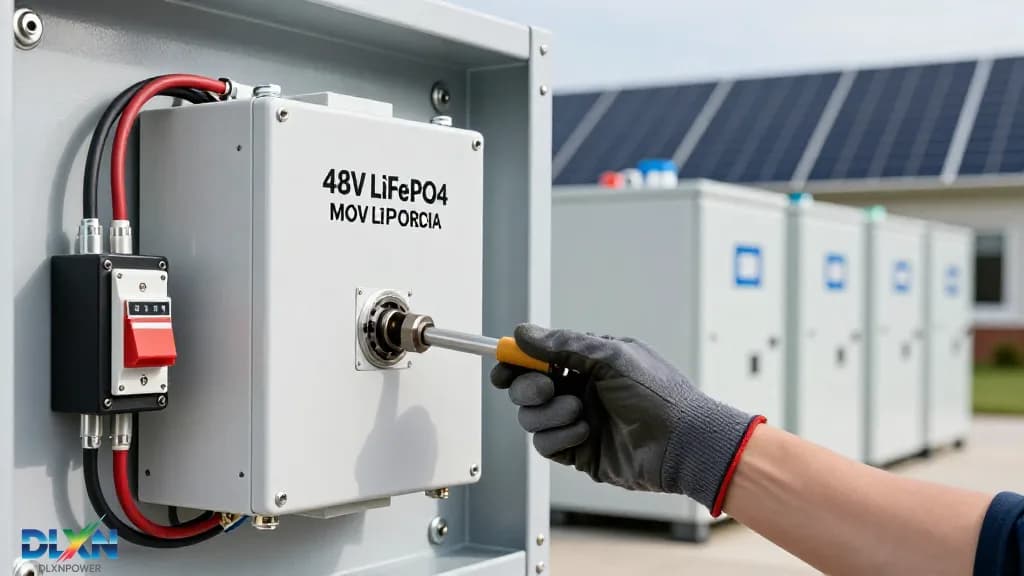
Correctly sized DC cabling prevents voltage drop and thermal stress. For a 48 V, 5 kW inverter, maximum DC current reaches about 104 A before surge conditions. Use copper cable of at least 35 mm² for runs under 5 m, stepping up to 50 mm² for longer distances, and keep total voltage drop below 2%. Terminate all cables with crimped lugs — never soldered joints, which creep and loosen under thermal cycling. Torque busbar connections to the manufacturer's specification, typically 8–12 Nm for M8 hardware, and re-check torque after the first 24 hours of operation. Loose terminations remain the single most common cause of field failures and battery fire incidents in residential systems.
Overcurrent protection belongs in every string. Each parallel branch requires a fuse or DC-rated breaker sized at 1.25× the maximum continuous current and matched to the cable's ampacity. The main battery disconnect must be a DC-rated device capable of interrupting fault current; in North American practice, a UL-listed battery disconnect is required within 3 m of the pack. When first connecting the battery to a capacitive inverter input, use a pre-charge resistor circuit — typically 5–10 Ω rated for 1 kW for 1–2 seconds — to limit inrush current and prevent welding the contactors. Never rely on the BMS as the sole disconnecting means; a mechanical, manually operated disconnect must always intervene between the pack and the inverter.
Inverter Integration and Communication Protocols
The battery and inverter must agree on voltage, current and state of charge before the first charge cycle. Most hybrid inverters support both 48 V LFP and high-voltage battery architectures, so confirm the pack's communication interface — typically CAN bus, RS-485 Modbus, or both. A protocol mismatch triggers audible alarms, derating, or refusal to charge. Configure the inverter charge profile to the BMS's recommended maximum: for a 16S LiFePO₄ pack, that is 57.6 V at 3.6 V per cell, with a nominal storage voltage of 54.4 V. Set the grid cut-off and restart thresholds to respect the battery's operating SOC window. These parameters directly affect cycle life and should be entered carefully rather than left at inverter factory defaults.
Real-world installations demonstrate that payback and reliability hinge on firmware alignment. Check that the battery pack and inverter firmware are both current before commissioning. Mismatched software versions between a new pack and a three-year-old inverter are a known trigger for SOC drift, premature balancing cycles and phantom low-voltage disconnects. Many hybrid systems are now sold with the BMS and inverter already profile-matched from the factory; in those cases, restrict manual settings to site-specific values such as usable capacity and standby charge current. DLXN's [inverter integration notes](/tech/inverters-1) document the exact register maps for common CAN and Modbus implementations. After any firmware update, run a full charge-discharge cycle to re-baseline the SOC.
Commissioning, Safety Checks and Preventive Maintenance
Commissioning follows a strict sequence. First, measure insulation resistance at every module with a megohmmeter before closing the main breaker — values must exceed 1 MΩ. Second, charge the pack to 100%, hold for two hours, and verify cell balance; a ±20 mV spread between cells is acceptable on a new pack. Third, conduct a controlled load test at 0.2 C (48 A for a 240 Ah bank), recording voltage sag, cell temperatures and BMS-reported SOC against actual discharge. Finally, run the BMS auto-registration sequence with the inverter and confirm that the monitoring dashboard shows accurate real-time SOC, current and module temperatures. Sign and date the commissioning checklist; this document becomes the baseline for all future troubleshooting.
Ongoing maintenance is lighter than lead-acid but not optional. Torque-check every busbar connection at six-month intervals, wipe dust from terminals and vents quarterly, and periodically charge the pack to 100% to rebalance cells and recalibrate SOC estimation. Retain the full commissioning report — torque values, firmware versions, insulation readings — since this documentation accelerates warranty claims and diagnostics. Larger installations benefit from cloud-based fleet monitoring that flags deviation trends before failures occur. DLXN's [project portfolio](/projects) demonstrates how disciplined installation and documentation practices translate into systems that pass third-party inspections and comfortably reach their 10-year, 6,000-cycle design life.