
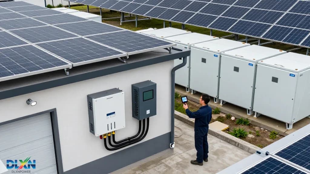
Site Assessment and Pre-Installation Planning
Before any hardware is mounted, a rigorous site assessment determines system viability, safety, and performance. Begin by evaluating the physical location: the battery unit must be installed on a fire-resistant surface (concrete or steel) with a minimum clearance of 300 mm on all sides for airflow and maintenance access. The ambient temperature range for most lithium-ion systems is 0°C to 45°C; exceeding this reduces cycle life by up to 20% per 10°C above 25°C, according to NREL studies. For outdoor installations, verify the enclosure’s IP rating—IP65 or higher is recommended for dust and water ingress protection, as seen in the [DLXN Helio2](/helio2) series.
Next, conduct a load profile analysis using 12 months of utility bills or a smart meter data export. This determines daily energy consumption in kWh, peak power demand in kW, and the critical loads that require backup during outages. For example, a typical U.S. home consumes 30 kWh/day with a 7 kW peak, but a home with electric vehicle charging may double both figures. Document the main panel capacity (100 A, 200 A, or 400 A) and the available breaker slots, as the battery will require a dedicated double-pole breaker rated at 125% of the inverter’s continuous output current.
Finally, verify local electrical codes and utility interconnection agreements. In the U.S., this means compliance with NEC Article 706 (Energy Storage Systems) and UL 9540 certification. In the EU, EN 50549 and VDE-AR-N 4105 apply. Many utilities require a permit and an interconnection application before grid-tied operation; failure to secure this can result in fines or system disconnection. Real-world example: California’s Title 24 mandates that new homes include solar-plus-storage, but installations without proper permits face retroactive rejection—so plan documentation early, referencing resources like [DLXN’s technical documentation](/tech).
System Sizing and Battery Chemistry Selection
Sizing a battery storage unit is a balancing act between energy capacity (kWh), power rating (kW), and depth of discharge (DoD). For backup applications, size the battery to cover critical loads for 24–48 hours. Formula: Battery capacity (kWh) = Daily critical load (kWh) × Days of autonomy ÷ DoD. For a home with 10 kWh/day critical load and 2 days autonomy at 90% DoD, you need 22.2 kWh usable capacity. For self-consumption optimization (shifting solar generation to evening), size the battery to 1.5–2× the average daily solar surplus. A 10 kW solar array producing 40 kWh/day with 50% surplus typically pairs with a 20–30 kWh battery.
Battery chemistry is the next critical decision. Lithium iron phosphate (LFP) dominates the market—over 60% of residential storage shipped in 2023 used LFP, per S&P Global—due to its 4,000–6,000 cycle life at 80% DoD and superior thermal stability (decomposition temperature >270°C vs. ~150°C for NMC). Nickel manganese cobalt (NMC) offers higher energy density (200–250 Wh/kg vs. 160–180 Wh/kg for LFP) but degrades faster and requires more thermal management. For stationary storage, LFP is the recommended default. Check the [DLXN lithium battery range](/products/lithium-battery) for LFP modules with integrated battery management systems (BMS) that monitor cell voltage, temperature, and state of charge at 10 Hz intervals.
Also consider the inverter’s DC voltage range. Most residential storage systems operate at 48 V (low voltage) or 400 V (high voltage). Low-voltage systems are simpler and safer for DIY but limited to ~15 kW power; high-voltage systems reduce cable losses (I²R) and support larger loads but require professional handling. Match the battery’s nominal voltage to the inverter’s MPPT range—for example, the [DLXN inverters](/tech/inverters-1) support 40–60 V and 350–500 V configurations. Lastly, plan for future expansion: choose a modular battery system that allows adding capacity in 5 kWh increments without replacing the base unit.
Electrical Integration and Inverter Interconnection
The electrical integration phase connects the battery to the solar array, inverter, and main electrical panel. The standard topology for AC-coupled systems: solar panels → solar inverter → main panel → battery inverter → battery. This allows retrofitting storage to existing solar without rewiring the DC side. DC-coupled systems (solar → charge controller → battery → inverter) are more efficient (up to 97% vs. 93%) but require a hybrid inverter. For new installations, DC coupling reduces component count and cost by 10–15%, according to the Rocky Mountain Institute.
When wiring the battery, use copper conductors rated for 90°C insulation and size them per NEC Table 310.15(B)(16). For a 48 V, 5 kW system drawing 104 A, use 2 AWG wire with a 125 A breaker. Torque all connections to manufacturer specifications—typically 10–15 Nm for battery terminals—and apply anti-oxidation compound on aluminum-to-copper junctions. Install a DC disconnect within 1.8 m of the battery to enable safe servicing. Ground the battery chassis to the main grounding electrode system with a 6 AWG bare copper wire, ensuring continuity below 0.1 Ω.
Inverter interconnection requires configuring the battery inverter’s communication with the solar inverter. Use Modbus RTU over RS-485 or CAN bus for real-time data exchange—this allows the system to manage charging rates based on solar production and load demand. Set the charging profile to match the battery’s recommended C-rate (e.g., 0.5C for LFP means a 10 kWh battery charges at 5 kW). Program the discharge cut-off at the BMS’s minimum voltage (typically 2.5 V/cell for LFP) to prevent over-discharge damage. For grid-tied systems, configure the inverter to export only surplus power after battery charging, avoiding penalties for backfeeding during peak hours. Reference the [DLXN battery storage technical page](/tech/battery-storage-1) for detailed wiring diagrams and communication pinouts.
Safety Protocols and Fire Mitigation
Safety is non-negotiable in battery storage installation. Lithium-ion batteries store significant energy—a 20 kWh unit contains the equivalent of 500 g of TNT—so thermal runaway prevention is paramount. Install smoke detectors and a heat sensor (rated for 70°C trigger) within 1 m of the battery. For indoor installations, ensure the room has a fire-rated door (minimum 1-hour rating) and a ventilation rate of 6 air changes per hour to dissipate any off-gassing. Outdoor installations should maintain a 1.5 m separation from combustible materials and property lines, per IFC 1207.
Personal protective equipment (PPE) during installation must include Class 0 insulated gloves (rated to 1000 V), safety glasses, and arc-rated clothing (minimum 4 cal/cm²). Use insulated tools rated for the system voltage. Before energizing, verify zero voltage with a CAT III multimeter and lock out all disconnects. For systems above 50 V DC, post warning signs and provide a remote emergency shutdown switch accessible from outside the room. In the event of thermal runaway, do NOT use water—use a Class D fire extinguisher (copper or sodium chloride based) or let the battery burn in a controlled area, as water can cause hydrogen gas generation.
Real-world safety data: The UL 9540A test method evaluates cell-level thermal runaway propagation. Systems that pass this test with no propagation beyond the module are rated for closer spacing and indoor installation. As of 2024, over 90% of certified residential storage units pass this test, but installation errors—particularly loose connections causing arcing—account for 40% of field failures, per the Electric Power Research Institute. Always perform a thermal imaging scan of all connections after initial energization to detect hot spots above 10°C delta from ambient.
Commissioning, Testing, and Performance Verification
Commissioning transforms a wired system into a functional asset. Begin with a visual inspection: verify all labels, torque marks, and cable routing. Perform a continuity test on all conductors and a megger test (insulation resistance) at 500 V DC—resistance must exceed 1 MΩ. Then, power up the BMS first, allowing it to balance cells for 30 minutes. Check cell voltage variance: it must be within ±0.05 V across all cells for LFP. If variance exceeds this, run a balancing cycle before proceeding.
Next, conduct a controlled charge/discharge test. Charge the battery at 0.2C (e.g., 2 kW for a 10 kWh unit) and record the time to reach 100% state of charge (SoC). Calculate actual capacity: Capacity (kWh) = Charge power (kW) × Time (hours) × Efficiency factor (0.95). Compare to the nameplate rating—a deviation above 5% indicates a faulty cell or BMS misconfiguration. Then discharge at 0.5C to the cut-off voltage, verifying that the BMS terminates at the correct SoC (typically 5–10%). Log all data for warranty registration.
Finally, verify grid interaction. For grid-tied systems, confirm that the inverter synchronizes with grid frequency (60 Hz ± 0.5 Hz) and voltage (240 V ± 10%). Test islanding protection by disconnecting the grid—the inverter must shut down within 2 seconds, per IEEE 1547. Reconnect and verify transition. For backup mode, simulate a grid outage and measure transfer time (should be < 10 ms for UPS-like operation). Document all test results and provide the homeowner with a commissioning report, including the [DLXN project reference](/projects) for future service.
Maintenance, Monitoring, and Longevity Optimization
A properly maintained battery storage unit lasts 10–15 years, but neglect can halve that. Establish a quarterly maintenance schedule: inspect terminals for corrosion or loosening (retorque to spec), clean air filters, and check for any bulging or discoloration of the battery casing. Annually, perform a capacity test (as described in commissioning) and update the BMS firmware—manufacturers release updates that improve charging algorithms and extend cycle life by 3–5%.
Monitoring is essential for proactive management. Install a monitoring gateway that tracks SoC, state of health (SoH), temperature, and charge/discharge cycles in real-time. Set alerts for SoH below 80% (end of useful life for most warranties) or cell temperature above 45°C. Many systems offer smartphone apps—[DLXN’s monitoring platform](/about) provides cloud-based dashboards with 15-minute data resolution and predictive maintenance alerts. For optimal longevity, program the BMS to maintain SoC between 20% and 80% for daily cycling; reserve 100% charge for backup readiness. This "depth of discharge management" extends cycle life by up to 40%, according to a 2023 study in the Journal of Energy Storage.
Environmental factors also affect longevity. For outdoor units, ensure the enclosure’s cooling fan is unobstructed—dust buildup reduces cooling efficiency by 30%, accelerating degradation. For indoor units, maintain ambient humidity below 70% to prevent connector corrosion. Finally, review your utility’s net metering policy annually; some utilities are shifting to time-of-use rates, which may require reprogramming the battery’s charge/discharge schedule to maximize savings. A well-maintained system not only delivers reliable backup power but also provides a return on investment of 7–10 years, with federal tax credits (e.g., 30% ITC in the U.S.) shortening payback further. For detailed maintenance checklists and firmware updates, consult the [DLXN contact page](/contact) for local support.